1. Introduction
1.1. Aircraft
Grumman F9F-8 Cougar
Carrier-based fighter / fighter-bomber (information in Wikipedia) U.S. Navy. BuNo 141123 / E208. VF-61 squadron.
USS Intrepid (CV-11), at sea, 1956.
1.2. Story
An F9F-8 Cougar jet of Fighter Squadron 61 aboard the USS Intrepid is on the carrier's catapult, ready to be launched on a routine training mission.
1.3. Model Kit
F9F-8 Cougar from Hasegawa (kit # 01619), 1:72 scale.
2. Kit Overview
The kit is very old (reportedly first tooled by Hasegawa in 1978) but surprisingly accurate for its age. The quality of moulds and the overall geometry are very good. The list of noticeable inaccuracies (the ones that must be corrected) is not very long; it includes main wheels; speed brake panels; aft end of the horizontal stabilizer fairing; IFR probe tip. Also, the layout of parts does not allow, without some surgery work, to build an early variant – the one without the intake splitter plates.
As it is typical with Hasegawa, there isn't much either in the cockpit or inside the wheel wells. A number of small details found on a real F9F-8 are missing too, but that is to be expected for a kit this old.
3. Construction
3.1. Building
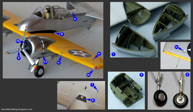
This is the list of enhancements that I have added to what was in the box:
1) Various fuselage inlets and vents were cut out (indents plus dark wash would not suffice to realistically imitate these, in my view). One incorrect inlet (fuselage rear, bottom right side) was filled. A couple of bulging inlets were also added.
2) Some plastic surgery had to be done to the engine intake channels and fuselage sides in order to represent an early Cougar without the intake splitter plates.
3) An excellent aftermarket cockpit set was installed (set # 7205 by the Czech firm CMR), comprising resin and photo-etched parts to give adequate cockpit and under-canopy detail.
4) The tail end of the fairing of the horizontal stabilizer must be made taller – and slimmer – than it is on the kit (o → 0).
5) My Cougar was to be presented as ready to be launched – on a catapult, with its engine running. Therefore, the two pairs of auxiliary air intake doors on the upper fuselage had to be shown open. It also meant that at least a sketch of the interior visible through these doors had to be modelled (which, in the end, has turned out to be nearly invisible).
6) On a Cougar before launch, both the outboard and the inboard flaps are lowered (a photographic proof: link). The cutting-out of the outer flaps was a relatively straightforward operation. 7) For the lowered inboard flaps, the respectively revealed interior had to be scratch-built.
8) The kit's main landing gear wells are too shallow. They had to be deepened for accuracy, and a sketch of interior was also added.
9) Nose landing gear leg was entirely scratch-built, and the main landing gear legs were enhanced with some minor details (brake lines, tie-down rings).
10) Correct landing gear wheels were taken from a resin set #7291 manufactured by Aires.
11) Landing gear doors had to be scratch-built from thin plastic, as the respective kit parts are too thick.
12) Custom-made photo-etched speed brake panels replaced the kit's inaccurate plastic items. The speed brakes are of course closed, as it should be on an operational, stationary Cougar in normal conditions.
13) Scratch-built tail skid was added. Note that it is normally extended on a stationary Cougar.
14) Wingtips were detailed with small round ram-air inlets (leading edge) and fuel vent outlets (trailing edge).
15) Multiple other tiny items were scratch-built and installed: a) intricately shaped barrier guard; b) gun barrels; c) IFR probe tip; d) Pitot tube; e) catapult bridle hook and catapult holdback ring; f) tailhook; g) fuel drain pipe.
16) As usual, external lights required much work – in the 1:72 scale the kit manufacturers typically ignore this aspect. For the Cougar, the following has to be done:
a) clear white dorsal navigation light, teardrop shaped;
b) opaque white and orange tail navigation lights, round;
c) carrier approach lights cluster – port wing root only
d) navigation lights – red and green coloured lamps inside clear wingtip caps;
e) navigation lights – red and green teardrop shapes on wing upper sides;
f) circular blue formation lights – wing undersides.


For amusement's sake, I counted all the bits that went into my model. The grand total is 195, 19 parts are from the Hasegawa kit, 30 parts are from aftermarket sets, and the remaining 146 pieces were scratch-made (using plastic, metal wire and metal foil).
3.2. Painting & Markings
The aircraft wears the standard U.S.Navy Light Gull Grey over Insignia White camouflage scheme of the period. Miscellaneous markings are done in accordance with historical photographs and comprise:
- Aluminum-colored leading edges of the wing, the horizontal stabilizer and the tail fin.
- Black anti-glare panel in front of the canopy.
- Insignia Red intake lips and flap wells interior.
- Grey wing walkways (a shade darker than Light Gull Grey, yet not as dark as Dark Gull Gray) with black outlines.
- Bare metal jet exhaust pipe.
Also note the following peculiar aspects:
- The horizontal stabilizer was painted Insignia White overall, and not just the elevators.
- A separate wing trimmer tab was present only on the left wing and was painted Insignia White.
- Black bands on speed brake panels.
- Operational F9F-8 fighters did not have the landing gear door edges painted Insignia Red (this practice was only introduced in 1959).
The decal that comes inside the box is typical for "classic" Hasegawa kits: extra thick layer, white color printed as cream, plus some cracking due to old age. And in any case it doesn't cover the variant that I wanted – a VF-61 grey & white bird (the Hasegawa's decal is for a dark blue aircraft). Therefore I had to use an aftermarket decal: it came from a multi-subject set #CTA-006 ("Jolly Rogers Timeline") produced by a small vendor named Cut then Add. In this set, the items intended for the F9F-8 are usable, although with a couple of issues. Firstly, the designer of this decal makes the same – unreasonable – premise as Hasegawa has done: that the decals intended to represent the yellow parts of the trim can cover such complex, curved shapes as the nose cone, the wing tips or the stabilizer fairing. That they definitely cannot. Therefore for the yellow trim you must use paint, and the decal will facilitate the thin black outline only (which is impossible to paint). Unfortunately, the thin black outline intended for the nose cone is incorrect (too small), and here I had to improvise with a piece of self-printed decal.
The national insignia decals came from a generic sheet produced by Techmod, as the blue on the CtA decal is too light.
3.3. Presentation
<to be detailed later>
4. Reference Data
[1] General information on the Grumman Cougar in Wikipedia: link [2] F9F Cougar in Detail & Scale | In Detail & Scale Series # 16 | Aero Publishers Inc., 1983.
[3] Grumman F9F-6/7/8 Cougar | Naval Fighters Series # 66 | Ginter Books, 2005.
[4] Navy & Marine Fleet Single-Seat F9F Cougar Squadrons | Naval Fighters Series # 69 | Ginter Books, 2006.
5. Notes
5.1. Many modellers equip their Cougars with 4 Sidewinder missiles and 2 external fuel tanks – obviously, because this is what the kit manufactures are suggesting in their instruction sheets, and also because many model builders enjoy loading their creations with as many weapons as possible.
Yet there is no photographic proof that such load was actually carried by operational F9F-8 Cougars.
I have counted all photographs of operational F9F-8 Cougar fighters that I was able to find (from books like Naval Fighters, Squadron/Signal, In Detail & Scale and various online galleries): there are slightly more than 300, and only 1 photograph shows an operational Cougar with Sidewinder missiles (with just two AIM-9Bs, in fact). And no, this is not because the set of available photographs is not a representative one. This is because an operational Cougar with Sidewinder missiles was indeed a rarity.
The fact that aircraft type "A" was technically capable of carrying weapon (or, more broadly, external stores) load "W" does not automatically mean that this aircraft type "A", while serving with squadron "S" during time period "T", was in fact carrying this weapon load "W".
There are such things as: a) logistics (actual availability of particular weapons / stores); b) requisite training of personnel; c) specific tasks set for a particular unit (squadron).
The first operational AIM-9B missiles were received by the operational squadrons of the U.S.Navy in mid-1956. By that time the F9F-8 variant was not very old – it has entered squadron service in late 1954. But it must be remembered that from the point of view of the Navy's top brass, the Cougar as a type was an interim solution. It was only in service because the other fighter projects – the F7U Cutlass, F3H Demon and F4D Skyray – have been much delayed. The year 1954 saw the entry into service of the F7U-3M Cutlass, and the 1956 – of the FJ-3M Fury, F3H-2 Demon and F4D-1 Skyray. The Cutlass is outside our area of interest here, as it was only capable of carrying the Sparrow I missile, but the other three types were envisaged as missile fighters equipped with the Sidewinder (and also the Sparrow, in the Demon's case). The squadrons "coming online" with these new types waited for the missile, and its production, initiated only recently, could not obviously satisfy all units at once.
By that time, the F9F-8 was already perceived as a multi-role plane, with more emphasis put on its light attack capability. So by 1956 the F9F-8, while still in service with many squadrons, was already slated for replacement – either with the new types of fighters already mentioned, or with the new types of light attack planes, such as the FJ-4B Fury and the A4D-1 Skyhawk. After all, within each USN Carrier Wing there could only be a limited number of squadrons, because an aircraft carrier could only embark a given number of planes.
Thus, there was very little sense, at that point, to allocate the time and the resources (in particular, for respective personnel training) required to actually broaden the mission of each of the existing Cougar squadrons with that of a missile-fighter, even if the production tempo of the missiles was able to support this growth.
So the bottom line is this: it is most probable that very, very few of the operational squadrons flying the F9F-8 Cougar have ever received the Sidewinder. And it is most improbable that the VF-61 'Jolly Rogers' squadron – the one beloved by scale modellers, – which only flew the F9F-8 variant for a few months (between January and September 1956), has seen the Sidewinder missiles at all.
5.2. It is very sad to observe the decline of Hasegawa as a designer and manufacturer of aircraft model kits. Once, Hasegawa was a byword for quality and finesse among scale modellers. Their aircraft kits were prized, and many have held the distinction of being "the very best of" a given subject for years.
And now? Quality is still present in their kits, but there does not seem to be any progress. There is no innovation: their latest kits do not offer any visible improvement in terms of detail, finesse and engineering over those dating from the 1980s and the 1990s. Other manufacturers (from such diverse countries as Czechia, Poland, UK, PRC, Ukraine) are now way ahead of Hasegawa.
And what does Hasegawa actually produce these days? The last of their really new (new-tool) aircraft model kits was released in 2017 – that was the 1/72 Kawanishi H8K2. Their monthly news are filled with old aircraft and car models first issued decades ago and being re-boxed with new decals, plus some fantasy contraptions ("anime", apparently?), plus figurines of half-naked women.
Information from the well-known scale modelling database site
Scalemates indicates that since 2020
Hasegawa has released nearly 150 new-tool items, from which there are 0 aircraft kits, 0 ships, 14 cars, and >95 figures of women. Judging by this, Hasegawa is hardly a manufacturer of scale model kits anymore. Rather, their main focus appears to be on producing female figurines. A downfall, in my opinion.
5.3. I wonder whether, in this age, anyone still actually reads the kits' instruction sheets...
The instruction for this particular kit contains some truly bizarre statements. The tiny text of no more than ten lines claims that the Cougar was "the first swept wing fighter in the world to actually participate in air combat", was "supersonic" and was "the most formidable of all carrier-based aircraft in the world at the time".
Whatever the age of the model kit, there is no excuse to propagate such nonsense. The first swept-wing fighters to see combat were of course the German Me 163 and Me 262 of the WWII fame. The Grumman Cougar fighter saw no combat use, and neither was it supersonic.
As for being "the most formidable"... This could be said to be true only if you consider an extremely narrow time band – between 1953 and 1955. Within this short period, the Cougar was probably a better performer than the other in-service carrier-based fighters, such as the F9F-5 Panther, F2H-3 Banshee, the British Sea Vampire, Sea Venom and Sea Hawk. Afterwards, more capable carrier planes began to enter service with the U.S.Navy, and very soon they completely superseded the Cougar in the fighter and fighter-bomber roles. But if the field of view is widened by removing the carrier-based restriction, then we see that there was nothing particularly "formidable" in the Cougar at all: it was a perfectly ordinary day-only light fighter / fighter-bomber, on par with its contemporaries such as the British Hawker Hunter, the French Dassault Mystère IV and the Soviet MiG-17. The Cougar was only employed in significant numbers as a fighter because the other fighters of the U.S.Navy – those that have been designed to be a bit more formidable, such as the F7U Cutlass, F3H Demon and F4D Skyray – were handicapped or delayed (due to problems with the engine manufacturer Westinghouse, whose supposedly super-powerful engine has turned out to be a complete and utter failure).


_in_March_1965.jpg)
_on_25_April_1956.jpg)
_on_6_June_1964.jpg)
_(26044118656).jpg)
.jpg)